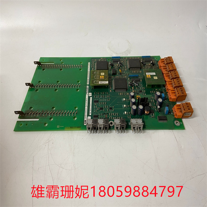
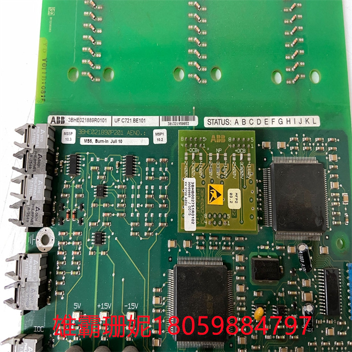
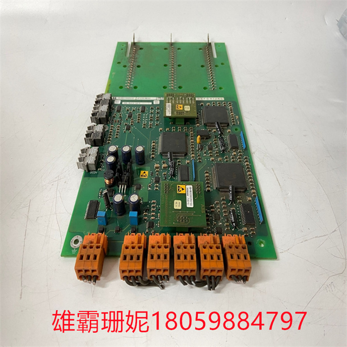
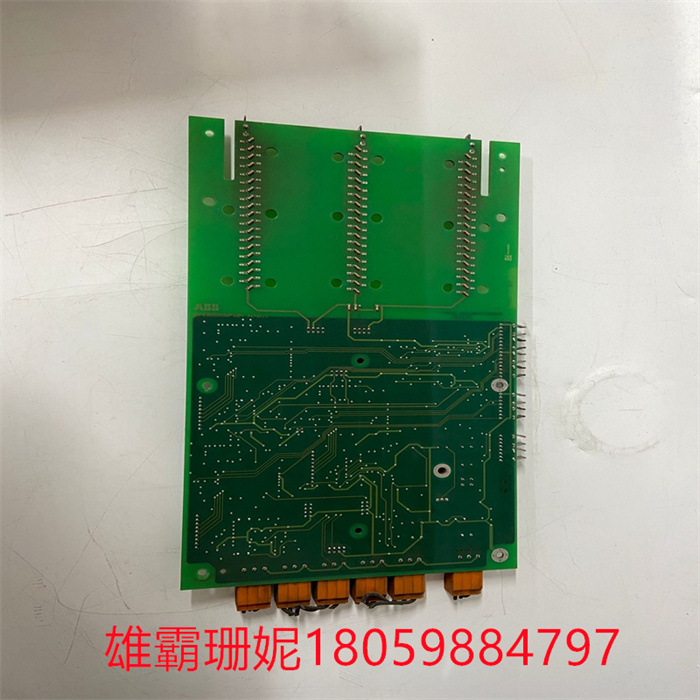
ABB UFC721BE101 3BHE021889R0101 可控硅触发板
ABB UFC721BE101 3BHE021889R0101 可控硅触发板
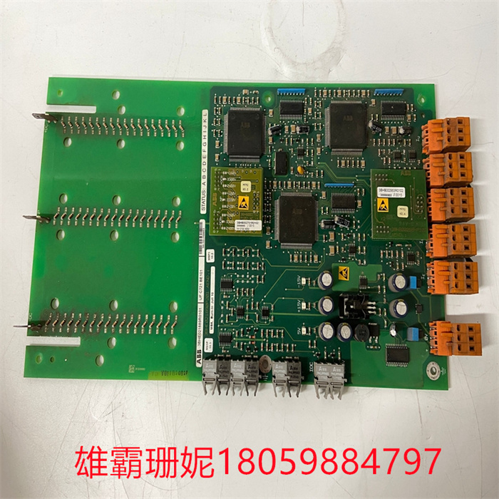
ABBUFC721BE1013BHE021889R0101ABBUFC721BE1013BHE021889R0101ABBUFC721BE1013BHE02输入输出回路调试(1)模拟量输入(AI)回路调试。要仔细核对0模块的地址分配:检查回路供电方式(内供电或外供电是否与现场仪表相一致用信号发生器在现场端对每个通道加入信号,通常取0、50%或100%三点进行检查。对有报警、联锁值的AI回路,还要在报警联锁值(如高报、低报和联锁点以及精度)进行检查,确认有关报警、联锁状态的正确性。(2)模拟量输出(AO)回路调试。可根据回路控制的要求,用手动输出(即直接在控制系统中设定)的办法检查执行机构(如阀门开度等),通常也取0、50%或100%三点进行检查同时通过闭环控制.检查输出是否满足有关要求。对有报警、联锁值的AO回路,还要在报警联锁值(如高报、低报和联锁点以及精度)进行检查,确认有关报警、联锁状态的正确性。(3)开关量输入(D)回路调试。在相应的现场端短接或断开 检查开关量输入模块对应通道地址的发光二极管的变化,同时检查通道的通、断变化。(4)开关量输出(DO)回路调试。可通过PLC系统提供的强制功能对输出点进行检查。通过强制,检查开关量输出模块对应通道地址的发光二极管的变化,同时检查通道的通、断变化。
2、回路调试注意事项(1)对开关量输入输出回路,要注意保持状态的一致性原则,通常采用正逻辑原则,即当输入输出带电时为"ON"状态 数据值为""反之,当输入输出失电时为“OFF"状态,数据值为"0”。这样,便于理解和维护。(2)对负载大的开关量输入输出模块应通过继电器与现场隔离,即现场接点尽量不要直接与输入输出模块连接。(3)使用PLC提供的强制功能时要注意在测试完毕后,应还原状态:在同一时间内,不应对过多的点进行强制操作,以免损坏模块。3、控制逻辑功能调试控制逻辑功能调试,需会同设计、工艺代表和项目管理人员共同完成。要应用处理器的测试功能设定输入条件根据处理器逻辑检查输出状态的变化是否正确,以确认系统的控制逻辑功能。对所有的联锁回路,应模拟联锁的工艺条件,仔细检查联锁动作的正确性,并做好调试记录和会签确认。检查工作是对设计控制程序软件进行验收的过程,是调试过程中最复杂、技术要求最高、难度最大的一项工作。特别在有专利技术应用、专用软件等情况下,更加要任细检查其控制的正确性应留有一定的操作裕度,同时保证工艺操作的正常运作以及系统的安全性、可靠性和灵活性。
ABB UFC721BE101 3BHE021889R0101 可控硅触发板
ABBUFC721BE1013BHE021889R0101ABBUFC721BE1013BHE021889R0101ABBUFC721BE1013BHE02 input/output circuit debugging (1) the analog input (AI) circuit debugging. To carefully check the address allocation of the 0 module: check the loop power supply mode (whether the internal power supply or the external power supply is consistent with the field instrument) Use the signal generator to add a signal to each channel at the field end, usually take 0, 50% or 100% three points for inspection. For the AI loop with alarm and interlock value, it is also necessary to check the alarm interlock value (such as high, low and interlock points and accuracy) to confirm the correctness of the alarm and interlock state. (2) Analog output (AO) loop debugging. According to the requirements of loop control, the actuator (such as valve opening, etc.) can be checked by manual output (that is, directly set in the control system), usually 0, 50% or 100% three points for inspection and through closed-loop control. Check whether the output meets the requirements. For the AO loop with alarm and interlock value, it is also necessary to check the alarm interlock value (such as high alarm, low alarm and interlock point and accuracy) to confirm the correctness of the alarm and interlock status. (3) Switching input (D) loop debugging. Check the change of the light emitting diode corresponding to the channel address of the switching input module by short-circuiting or disconnecting at the corresponding field end, and check the change of the channel on and off. (4) Switching output (DO) loop debugging. The output points can be checked through the forced function provided by the PLC system. By force, check the change of the light emitting diode corresponding to the channel address of the switching quantity output module, and check the change of the channel on and off.
(1) For the input and output circuits of the switching quantity, attention should be paid to maintaining the consistency principle of the state, usually using the positive logic principle, that is, when the input and output are energized, the state data value is "ON", and conversely, when the input and output are out of power, the state is "OFF" and the data value is "0". In this way, it is easy to understand and maintain. (2) The input/output module with large load switching quantity should be isolated from the field by relay, that is, the field contact should not be directly connected with the input/output module as far as possible. (3) When using the mandatory function provided by PLC, it should be noted that after the test is completed, the state should be restored: at the same time, it should not be forced to operate too many points to avoid damage to the module. 3, control logic function debugging control logic function debugging, need to be completed jointly with the design, process representatives and project management personnel. To apply the test function of the processor to set input conditions to check whether the change of output state is correct according to the processor logic to confirm the control logic function of the system. For all interlocking circuits, the process conditions of interlocking should be simulated, the correctness of interlocking action should be carefully checked, and debugging records should be made and countersigned for confirmation. Inspection is the process of acceptance of the design control program software, which is the most complex, the highest technical requirements and the most difficult work in the debugging process. Especially in the case of patented technology applications, special software, etc., it is more necessary to carefully check the correctness of its control should leave a certain operating margin, while ensuring the normal operation of the process operation and the safety, reliability and flexibility of the system.
ABB UFC721BE101 3BHE021889R0101 可控硅触发板


![6@GFX$A[~V[`PFQH]7(V1%T.jpg](https://www.xmxbdzsw.com/uploads/allimg/20230720/1-230H015352Aa.jpg)
| ABB | PM150V08 3BSE009598R1 |
| ABB | AI810 3BSE008516R1 |
| ABB | SC510 |
| ABB | PFVK135 |
| ABB | CMA120 3DDE300400 |
| ABB | 3BHL000986P7000 LXN1604-6 |
| ABB | TU830V1 |
| ABB | AI810 3BSE00851 6R0001 |
| ABB | DO820 3BSE008514R1 |
| ABB | DI810 3BSE008508R1 |
| ABB | TB820V2 3BSE013208R0001 |
| ABB | UFC760BE142 3BHE004573R0142 |
| ABB | TU831V1 3BSE013235R0001 |
| ABB | PPC907BE 3BHE024577R0101 |
| ABB | LDGRB-01 3BSE013177R1 |
| ABB | 5SHY3545L0014 |
| ABB | AI815 3BSE052604R1 |
| ABB | CI520V1 |
| ABB | AO2000-LS25 |
| ABB | CMA132 |
| ABB | XVC767AE102 3BHB007209R0102 |
| ABB | 3BHL000986P0006 |
| ABB | LDGRB-01 |
| ABB | LDGRB-01 |
| ABB | SPDSO14 |


