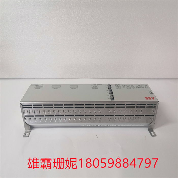
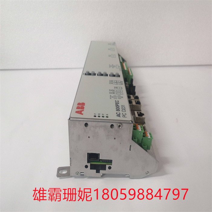
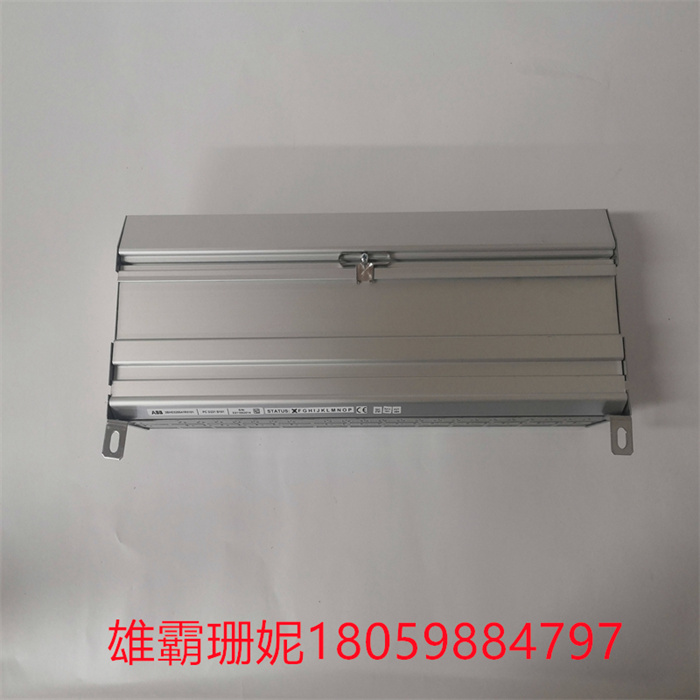
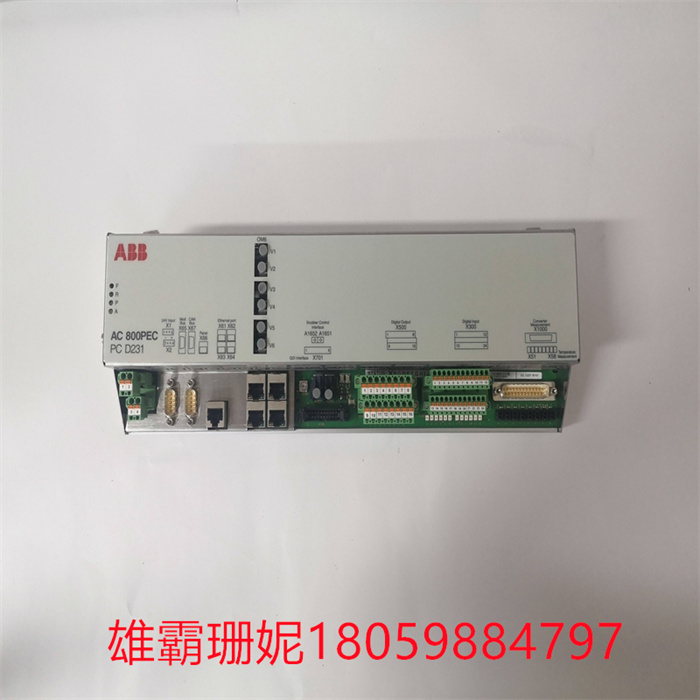
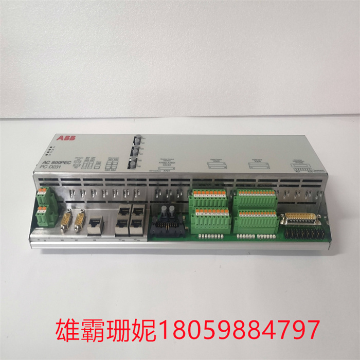
ABB PCD231B101 3BHE025541R0101 输入脉冲模块
If the PCB cabinet must be removed from the control, please follow the following precautions: Do not touch any part of the PCB except the edges. Do not touch electrical conductors, connectors or use conductive devices or operate components by hand. When replacing a PCB, keep the new PCB in a protective bag in antistatic plastic until you are ready to install it. Immediately remove the old PCB from the control cabinet and put it in an antistatic protective bag. In order to prevent damage to electronic components caused by operation, read and abide by the precautions in Woodward Manual 82715, Guide Electronic Control Devices, Printed Circuit Boards and Modules. Protective grounding (PE) must be connected to the back of the equipment, close to the labeled tag (or a similar unlabeled terminal point among the other three tags) to reduce the risk of electric shock. The connection will be made using thread forming screws. The connection provided by the train conductor must have a ring-shaped lug of appropriate size and a larger conductor less than or equal to 3.0 mm(12 AWG).如果必须从控件中移除PCB机柜,请遵循以下预防措施:除边缘外,请勿触摸PCB的任何部分。请勿触摸电导体、连接器或使用导电器件或用手操作部件。更换PCB时,将新PCB保持在防静电塑料中保护袋,直到你准备好安装它。立即从控制柜中卸下旧PCB后,将其放在防静电保护袋。为了防止操作引起的对电子部件的损坏,阅读并遵守伍德沃德手册82715,指南中的预防措施电子控制装置、印刷电路板和模块。保护接地(PE)必须连接至设备背面,靠近带有符号的标签(或其他3个标签中的1个类似的没有标签的终端点),以减少电击的风险。该连接将使用螺纹成形螺钉进行。列车长提供连接必须有一个适当尺寸的环形接线片和更大的导线小于或等于3.0 mm(12 AWG)。
ABB PCD231B101 3BHE025541R0101 输入脉冲模块
在用户程序执行阶段,PLC总是按由 上而下的顺序依次地扫描用户程序(梯形图)。在扫描每一条梯形图时, 又总是先扫描梯形图左边的由各触点构成的控制线路,并按先左后右、先上后下的顺序对由触点构成的控制线路进行逻辑运算,然后根据逻辑运算的结果,刷新该逻辑线圈在系统RAM存储区中对应位的状态;或者刷新该输出线圈在I/O映象区中对应位的状态;或者确定是否要执行该梯形图所规定的特殊功能指令。即,在用户程序执行过程中,只有输入点在I/O映象区内的状态和数据不会发生变化,而其他输出点和软设备在I/O映象区或系统RA存储区内的状态和数据都有可能发生变化,而且排在上面的梯形图,其程序执行结果会对排在下面的凡是用到这些线圈或数据的梯形图起作用;相反,排在下面的梯形图,其被刷新的逻辑线圈的状态或数据只能到下一个扫描周期才能对排在其上面的程序起作用。
In the user program execution stage, PLC always scans the user program (ladder diagram) in order from top to bottom. When scanning each ladder diagram, always scan the control circuit composed of contacts on the left side of the ladder diagram first, and perform logical operation on the control circuit composed of contacts in the order of first left and then right, first up and then down, and then refresh the state of the corresponding bit of the logic coil in the system RAM storage area according to the result of logical operation; Or refresh that state of the corresponding bit of the output coil in the I/O map area; Or determine whether to execute the special function instruction specified in the ladder diagram. That is, in the process of user program execution, only the state and data of the input point in the I/O image area will not change, while the state and data of other output points and soft devices in the I/O image area or the system RA storage area may change, and the program execution result of the ladder diagram ranked above will play a role in the ladder diagram ranked below that uses these coils or data; On the contrary, in the ladder diagram arranged below, the status or data of the refreshed logic coil can only work on the program arranged above it in the next scanning cycle.

