

IC200PWB001 增压器 安装在DIN导轨
【产品详情】
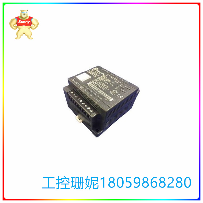
IC200PWB001是GE设计的VersaMax系列的增压器。 该IC200PWB001用于安装带有附加模块托架的额外电源。当电源安装在升压器载体上时,将向位于右侧的每个 I/O 模块供电,或直到下一个升压器电源。外部电源由 CPU 或 NIU 上的 AC 或 DC 电源与位于 IC200PWB001 上的电源共享。
IC200PWB001配备了两个 LED。PWR LED 指示连接的升压电源的功能运行正常。同样,OK LED 指示 CPU 或 NIU 以及连接的升压器电源工作正常。
将IC200PWB001安装在DIN导轨上需要DIN导轨电气接地,以提供EMC保护。用于IC200PWB001的DIN导轨尺寸为7.5mm x35mm。IC200PWB001可以轻松卡在DIN导轨上。 带电源的电源增压托架可放入 70 毫米深的隔间中。导轨的饰面必须未上漆,以提供耐久的饰面。某些应用需要最大的抗机械振动和冲击能力,这是通过面板安装实现的。
要卸下IC200PWB001,用户需要从 DIN 导轨上卸下托架。必须卸下连接托架的螺钉,如果托架安装在其他托架之间,则由于位于托架侧面的配对连接器,也必须卸下其他托架。DIN 导轨的闩锁片必须向外拉并倾斜才能正确拆卸。
GE Fanuc IC200PWB001 电源升压托架用于安装额外的电源,与系统中的其他模块托架串联。安装在升压器托架上的电源为位于设备右侧或向上的每个 I/O 模块供电,直到同一系统中的下一个升压电源。NIU 或 CPU 上的直流或交流电源以及升压器载体中存在的电源都应使用等效的外部电源。GE Fanuc IC200PWB001 电源增压器载体有 2 个 LED,分别是显示所连接升压电源功能状态的“PWR”LED 和显示 NIU 或 CPU 的功能状态的“OK”LED 以及连接的升压电源。
GE Fanuc IC200PWB001 电源增压托架应适当安装在 7.5 毫米 x 35 毫米的 DIN 导轨上。为确保DIN导轨提供EMC保护,应将其电气接地,表面应为导电耐腐蚀表面处理。为了提供抗机械冲击和抗振动性,IC200PWB001 电源增压托架应安装在面板上。电源升压器的尺寸为 66.8 毫米(2.63 英寸)x 133.4 毫米(5.25 英寸)x 70 毫米(2.75 英寸)。卸下 IC200PWB001 电源增压架时,用户需要通过卸下用于连接它的螺钉将其从 DIN 导轨上卸下。如果增压器托架安装在其他托架单元之间,用户将需要将其卸下,因为配套连接器位于侧面。为了正确拆卸增压托架,用户需要向外拉动 DIN 导轨闩锁片并将其倾斜。
IC200PWB001 增压器 安装在DIN导轨
【英文介绍】
The IC200PWB001 is a supercharger for the GE VersaMax family. The IC200PWB001 is used to install additional power supplies with additional module brackets. When the power supply is mounted on the booster carrier, power is supplied to each I/O module located on the right, or until the next booster power supply. The external power supply is shared between the AC or DC power supply on the CPU or NIU and the power supply located on the IC200PWB001.
The IC200PWB001 is equipped with two leds. The PWR LED indicates that the function of the connected booster power supply is functioning properly. Again, the OK LED indicates that the CPU or NIU and the connected booster power supply are working properly.
Mounting the IC200PWB001 on a DIN rail requires DIN rail electrical grounding to provide EMC protection. The DIN rail size for IC200PWB001 is 7.5mm x35mm. The IC200PWB001 can be easily stuck on the DIN rail. The power booster bracket with power supply can fit into compartments up to 70 mm deep. The finish of the guide rail must be unpainted to provide a durable finish. Certain applications require maximum resistance to mechanical vibration and shock, which is achieved through panel mounting.
To remove the IC200PWB001, the user needs to remove the bracket from the DIN rail. The screws connecting the bracket must be removed, and if the bracket is mounted between other brackets, the other brackets must also be removed due to the pairing connector located on the side of the bracket. The latch plate of the DIN rail must be pulled outward and tilted to remove correctly.
The GE Fanuc IC200PWB001 Power boost bracket is used to install additional power supplies in series with other module brackets in the system. The power supply mounted on the booster bracket powers each I/O module located to the right or up of the device until the next booster power supply in the same system. The DC or AC power supply on the NIU or CPU and the power supply present in the booster carrier should use an equivalent external power supply. The GE Fanuc IC200PWB001 power booster carrier has two leds, which are the "PWR" LED showing the functional status of the connected boost power supply and the "OK" LED showing the functional status of the NIU or CPU and the connected boost power supply.
The GE Fanuc IC200PWB001 power booster bracket shall be properly mounted on a 7.5 mm x 35 mm DIN rail. To ensure EMC protection for DIN rails, they should be electrically grounded and the surface should be electrically conductive and corrosion-resistant. In order to provide resistance to mechanical shock and vibration, the IC200PWB001 power boost bracket shall be mounted on the panel. The power booster measures 66.8 mm (2.63 in) x 133.4 mm (5.25 in) x 70 mm (2.75 in). When removing the IC200PWB001 power booster rack, the user needs to remove it from the DIN rail by removing the screws used to attach it. If the supercharger bracket is mounted between other bracket units, the user will need to remove it because the matching connector is located on the side. To properly remove the booster bracket, the user needs to pull the DIN rail latch outward and tilt it.
IC200PWB001 增压器 安装在DIN导轨


【其他型号推荐】
| FOXBORO CI626A 3BSE005023R1 | FOXBORO DCS | 模块 | FOXBORO 43AP-FA52C/TA-1A | FOXBORO DCS | 模块 |
| FOXBORO CI626A 3BSE005023R1 | FOXBORO DCS | 模块 | FOXBORO 43APFA45C | FOXBORO DCS | 模块 |
| FOXBORO CI570 | FOXBORO DCS | 模块 | FOXBORO 43APFA42NPC | FOXBORO DCS | 模块 |
| FOXBORO CI540 3BSE001077R1 | FOXBORO DCS | 模块 | FOXBORO 43AP-FA42N/PC | FOXBORO DCS | 模块 |
| FOXBORO CI532V04 | FOXBORO DCS | 模块 | FOXBORO 43AP-FA42N/PB-AA-1000 | FOXBORO DCS | 模块 |
| FOXBORO CI532V02 3BSE003827R1 | FOXBORO DCS | 模块 | FOXBORO 43APFA42N | FOXBORO DCS | 模块 |
| FOXBORO CI532V01 3BSE003826R1 | FOXBORO DCS | 模块 | FOXBORO 43APFA42DPC | FOXBORO DCS | 模块 |
| FOXBORO CI526 | FOXBORO DCS | 模块 | FOXBORO 43AP-FA42D/PC | FOXBORO DCS | 模块 |
| FOXBORO CI522A 3BSE018283R1 | FOXBORO DCS | 模块 | FOXBORO 43AP-FA42D/PB-BA | FOXBORO DCS | 模块 |
| FOXBORO CI522 3BSE012790R1 | FOXBORO DCS | 模块 | FOXBORO 43APFA42D | FOXBORO DCS | 模块 |
| FOXBORO CI520V1 | FOXBORO DCS | 模块 | FOXBORO 43AP-FA42C-TA1A | FOXBORO DCS | 模块 |