

GE IC200ETM001 扩展连接器 现场总线通信模块
【产品详情】
| 品牌 | GE发那科 |
| 系列 | Versamax的 |
| 零件编号 | IC200ETM001 |
| 品牌 | GE智能平台 |
| 公告 | IC200型 |
| 产品类型 | 扩展连接器 |
| 连接器 | 26 针母头连接器 |
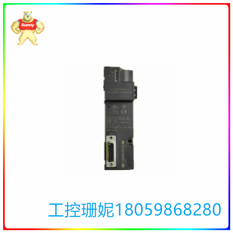
GE Fanuc Automation IC200ETM001模块是一个扩展连接器,可扩展 VersaMax PLC 以容纳多达 7 个额外的机架。每个额外的机架最多可容纳 8 个输入/输出模块,包括现场总线通信模块。它在模块前面带有一个 26 针母连接器。连接器用于将模块连接到扩展接收器模块。请务必在模块的左上角找到一个 16 针公头串行端口连接器。这是一个串行编程端口,用于将固件更新上传到相邻的 NIU。
IC200ETM001模块还自带高速扩展接口和2个LED指示灯,用于显示扩展接口的状态和模块的电源状态。电源 LED 指示模块正在从 CPU 或 NIU 提供 5V DC。它熄灭表示模块已与 CPU 或 NIU 分离或 CPU 供电中断。EXP TX LED 闪烁以指示扩展发射器和总线接收器模块之间的通信。如果两者之间没有通信,它将保持关闭状态。扩展接收器模块有两个模块:隔离模块 - ERM001 和非隔离模块 - ERM002。
扩展模块安装在DIN导轨上。然后,在同一个DIN导轨上,它连接到VersaMax CPU或NIU模块的左侧。它可以在扩展机架中连接多达 7 个接收器模块。整体扩展电缆长度取决于所使用的扩展接收器模块的类型。 隔离模块 ERM15 为 001 米,ERM750 为 002 米。
模块和托架应安装在 35mm x 7.5 mm DIN 导轨的同一部分上。为了正确接地,导轨必须具有未上漆的表面。建议将 DIN 通过螺钉固定在面板上,螺钉应彼此相距 6 英寸。标签首先插入位于模块左上角的小检修门内。 然后,扩展模块连接到位于扩展机架左端的DIN导轨上。安装过程中无需任何工具,因为模块可轻松卡入DIN导轨上。使用检修门下方的旋转开关选择扩展机架 ID(从 1 到 7)。 然后将电源模块连接到扩展接收器上,打开电源并观察 LED。
要卸下电源,请关闭机架电源并从扩展接收器模块上卸下电源。 此后,将 DIN 导轨上的扩展模块从其他模块上滑开。 最后,使用螺丝刀拧下模块并将其从 DIN 导轨上提起。
扩展模块最初设置为以 250 位/秒的数据速率运行,以达到扩展电缆的最大长度。如果总长度小于 250 米,并且系统中没有 ERM002 模块,则 VersaMax PLC 可以将速率调整为 1 Mbit/s。在 NIU I/O Station 中,数据速率保持不变,无法从其默认速率 250Kbits 进行调整。
GE IC200ETM001 扩展连接器 现场总线通信模块
【英文介绍】
The GE Fanuc Automation IC200ETM001 module is an expansion connector that extends the VersaMax PLC to accommodate up to seven additional racks. Each additional rack can accommodate up to 8 input/output modules, including fieldbus communication modules. It comes with a 26-pin female connector on the front of the module. Connectors are used to connect the module to the expansion receiver module. Be sure to find a 16-pin male serial port connector in the upper left corner of the module. This is a serial programming port used to upload firmware updates to adjacent NIU.
The IC200ETM001 module also comes with a high-speed expansion interface and 2 LED indicators to display the status of the expansion interface and the power status of the module. The power LED indicator module is supplying 5V DC from the CPU or NIU. If it is off, the module is separated from the CPU or NIU or the CPU power supply is interrupted. The EXP TX LED blinks to indicate communication between the extended transmitter and bus receiver modules. If there is no communication between the two, it will remain closed. The expansion receiver module has two modules: the isolated module - ERM001 and the non-isolated module - ERM002.
Expansion modules are mounted on DIN rails. Then, on the same DIN rail, it connects to the left side of the VersaMax CPU or NIU module. It can connect up to 7 receiver modules in an expansion rack. The overall expansion cable length depends on the type of expansion receiver module used. The isolation module ERM15 is 001 meters and the ERM750 is 002 meters.
The module and bracket shall be mounted on the same part of the 35mm x 7.5mm DIN rail. In order to be properly grounded, the rail must have an unpainted surface. It is recommended that the DIN be secured to the panel by screws, which should be 6 inches from each other. The label is first inserted into the small access door located in the upper left corner of the module. The expansion module is then connected to the DIN rail located at the left end of the expansion frame. No tools are required during installation, as the module can easily snap into the DIN rail. Use the rotary switch below the access door to select the extension rack ID (from 1 to 7). Then connect the power module to the expansion receiver, turn on the power and observe the LED.
To remove the power, turn off the rack power and remove the power from the expansion receiver module. After that, slide the expansion module on the DIN rail away from the other modules. Finally, use a screwdriver to unscrew the module and lift it from the DIN rail.
The expansion module was initially set to run at a data rate of 250 bits/SEC to reach the maximum length of the expansion cable. If the total length is less than 250 meters and there is no ERM002 module in the system, the VersaMax PLC can adjust the rate to 1 Mbit/s. In NIU I/O stations, the data rate remains unchanged and cannot be adjusted from its default rate of 250Kbits.
GE IC200ETM001 扩展连接器 现场总线通信模块


【其他型号推荐】
| FOXBORO cp60s | FOXBORO DCS | 模块 | FOXBORO 743CAAP | FOXBORO DCS | 模块 |
| FOXBORO CP60(P0961FR) | FOXBORO DCS | 模块 | FOXBORO 743CA-AF-1 | FOXBORO DCS | 模块 |
| FOXBORO CP60 P0961FR-0P | FOXBORO DCS | 模块 | FOXBORO 740RA-A3333-N | FOXBORO DCS | 模块 |
| FOXBORO CP60 P0961FR REV | FOXBORO DCS | 模块 | FOXBORO 740RA-A3333-ACNPQ1 | FOXBORO DCS | 模块 |
| FOXBORO CP60 P0961FR | FOXBORO DCS | 模块 | FOXBORO 740RAA3000CQ | FOXBORO DCS | 模块 |
| FOXBORO CP60 5000 | FOXBORO DCS | 模块 | FOXBORO 740RA-A3000-AC | FOXBORO DCS | 模块 |
| FOXBORO CP60 2500 | FOXBORO DCS | 模块 | FOXBORO 740CAA3133CCA | FOXBORO DCS | 模块 |
| FOXBORO CP60 1000 | FOXBORO DCS | 模块 | FOXBORO 731CA14 | FOXBORO DCS | 模块 |
| FOXBORO CP60 P0961FR | FOXBORO DCS | 模块 | FOXBORO 710D39112 | FOXBORO DCS | 模块 |
| FOXBORO CP60 | FOXBORO DCS | 模块 | FOXBORO 6DD1660-0AE0 | FOXBORO DCS | 模块 |
| FOXBORO CP40B P0961BC | FOXBORO DCS | 模块 | FOXBORO 6AV3607-1JC20-0AX1 | FOXBORO DCS | 模块 |
| FOXBORO CP40B | FOXBORO DCS | 模块 | FOXBORO 6AV3607-1JC20-0AX1 | FOXBORO DCS | 模块 |
| FOXBORO CP40A | FOXBORO DCS | 模块 | FOXBORO 66RC-OLA | FOXBORO DCS | 模块 |
| FOXBORO CP40 P0960JA | FOXBORO DCS | 模块 | FOXBORO 66DCOH1 | FOXBORO DCS | 模块 |