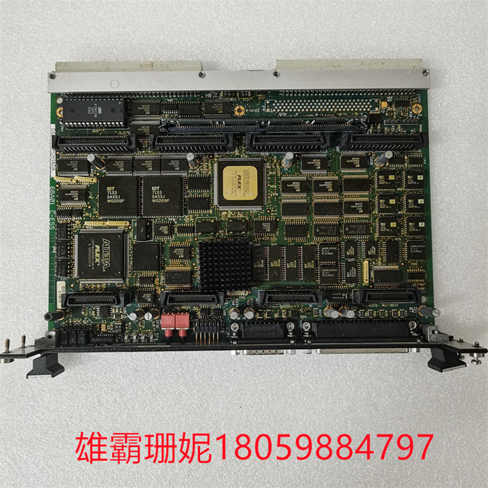
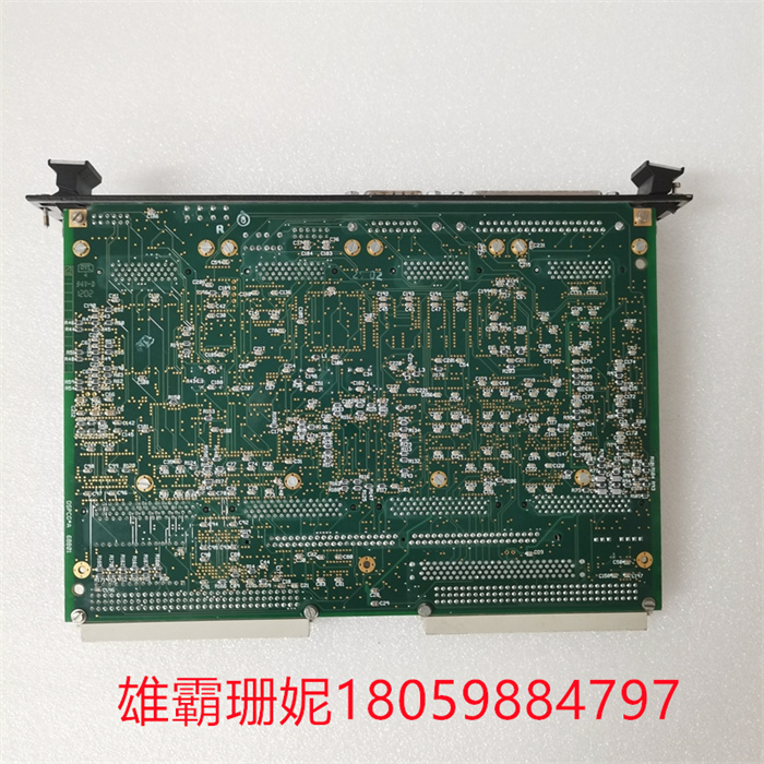
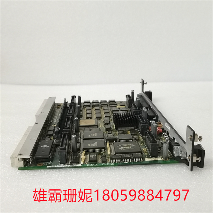
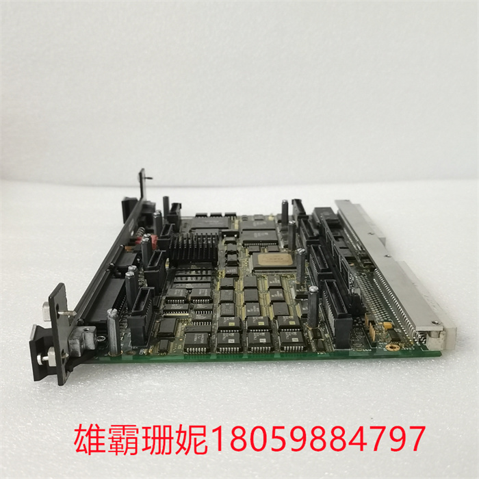
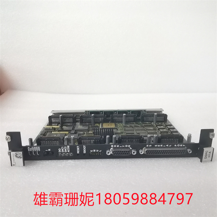
GE DS200DSPCH1ADA 输出模块
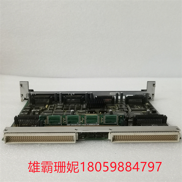
DS200DSPCH1ADA是GE开发的一款触点输入组隔离端子板。24 个干触点输入连接到带组隔离的触点输入 (TBCI) 端子板上的两个栅栏式端子块。对于接触激励,TBCI 与直流电源耦合。触点输入中的降噪电路可保护浪涌和高频噪声。
TBCI 支持单工和 TMR 应用程序,并与 VTCC/VCRC 一起工作。TBCI 连接到 VME 机架,其中 VCCC 或 VCRC 处理器板通过带有模制插头的电缆放置。该板的 TBCIH B 和 TBCIH C 变体均适用于 Mark VI,并且功能相同。标称电压为 24 V dc。
DS200DSPCH1ADA 安装
接线
将 24 路干接点输入的接线直接连接到端子板的两个 I/O 接线端子上。两个螺钉将这些块固定到位,并且可以将它们从电路板上拔下进行维护。每个块有 24 个端子,可容纳高达 #12 AWG 的电线。每个接线盒的左侧是一个连接到机箱接地的屏蔽接线板。
电源连接
使用插头 JE1 和 JE2 将 TBCI 连接到接触激励电压源。
布线连接
在单工系统中使用连接器 JR1 将 TBCI 连接到 I/O 处理器。使用连接器 JR1、JS1 和 JT1 将 TBCI 连接到 TMR 系统中的 I/O 处理器。根据 Mark VI、Mark VIe 或 Mark VIeS 系统的类型以及冗余级别,插入电缆或 I/O 包。
DS200DSPCH1ADA 操作
在信号输入点附近的每个输入端,滤波器可降低高频噪声并控制浪涌。H1 上的干触点输入由涡轮机控制的浮动 125 V 直流 (100-145 V 直流) 电源供电。在为每个触点输入供电之前,125 V 直流母线在配电模块中受到电流限制。如规格表中所示,H2 和 H3 变体使用较低的电压。
GE DS200DSPCH1ADA 输出模块
对接线板上的组件执行以下诊断测试:
测量激励电压。如果激励低于标称电压的 40%,I/O 组件/板会设置并锁定诊断警告。
作为测试,所有接线板的输入都设置为断开触点(故障安全)状态。任何未通过诊断测试的输入都会被强制进入故障安全模式,从而导致故障的产生。
如果来自该板的输入与来自所有三个板的 TMR 表决值不匹配,则会发出故障。
每个端子板连接器都有自己的 ID 设备,I/O 包/板会查询该设备。
GE DS200DSPCH1ADA 输出模块
DS200DSPCH1ADA 规格
通道数
24路接点电压输入通道
输入过滤器
4 毫秒硬件过滤器
能量消耗
在接线板上,20.6 W
DS200DSPCH1ADA is a contact input group isolation terminal board developed by GE. The 24 dry contact inputs are connected to two barrier terminal blocks on the contact input (TBCI) terminal board with group isolation. For contact excitation, TBCI is coupled with DC power supply. Noise reduction circuit in contact input can protect surge and high frequency noise.
TBCI supports simplex and TMR applications and works with VTCC/VCRC. The TBCI is connected to the VME rack, where the VCCC or VCRC processor board is placed through cables with molded plugs. Both TBCIH B and TBCIH C variants of this board are suitable for Mark VI and have the same function. The nominal voltage is 24 V dc.
DS200DSPCH1ADA installation
wiring
Connect the 24-way dry contact input wiring directly to the two I/O terminals of the terminal board. Two screws hold the blocks in place, and they can be removed from the circuit board for maintenance. Each block has 24 terminals and can accommodate wires up to #12 AWG. On the left side of each junction box is a shielded terminal block connected to the chassis ground.
Power connection
Use plugs JE1 and JE2 to connect TBCI to the contact excitation voltage source.
Wiring connection
Use connector JR1 to connect TBCI to I/O processor in simplex system. Use connectors JR1, JS1 and JT1 to connect TBCI to I/O processor in TMR system. According to the type and redundancy level of Mark VI, Mark VIe or Mark VIeS system, insert cables or I/O packages.
Operation of DS200DSPCH1ADA
At each input near the signal input point, the filter can reduce high-frequency noise and control surge. The dry contact input on H1 is powered by a floating 125 V DC (100-145 V DC) power supply controlled by the turbine. Before supplying power to each contact input, the 125 V DC bus is limited by current in the distribution module. As shown in the specification table, H2 and H3 variants use lower voltages.

