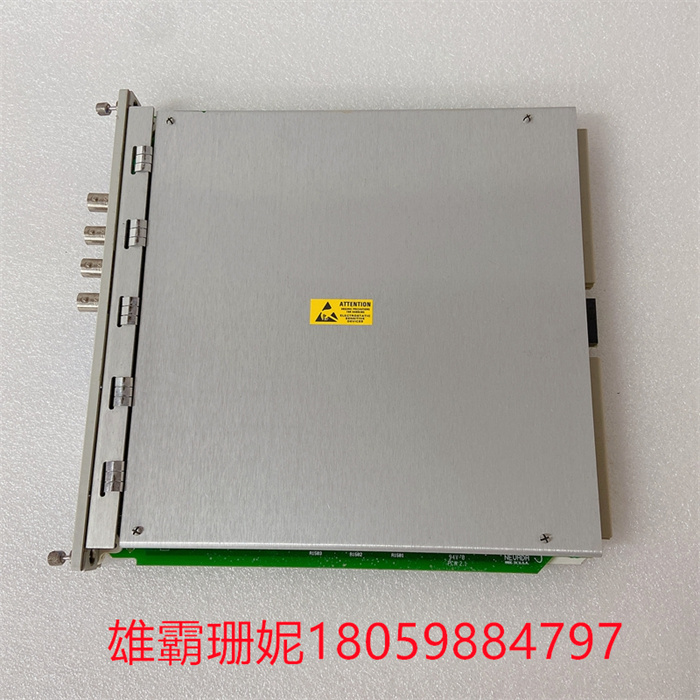
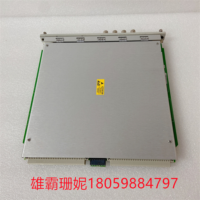
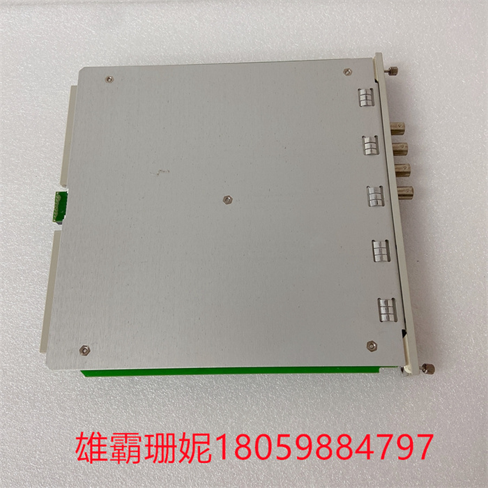
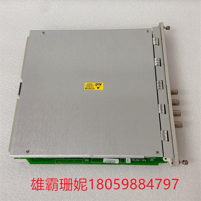
BENTLY 350040M 140734-01 输出模块数字
BENTLY 350040M 140734-01 输出模块数字
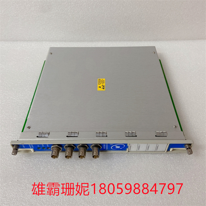
由跳闸单元216DB61控制。在每种情况下电路连接到由两个串联触点构成的端子上。14个信号继电器:二进制O/P单元216AB61控制。N/O触点并且继电器1…4的N/C触点连接到端子。该装置以24 V直流电供电,并提供冗余电源。保险丝F101(2 A快速,5 x 20 mm)安装在保护24 V电源不受装置短路的影响。在RE.216方案中,二进制信号可以具有以下值之一:逻辑“0”(固定值)=FALSE逻辑“1”(固定值)=真二进制输入值(216DB61、216EB61)双重指示信号;两个连续的二进制输入是组合。功能定义的二进制保护值(跳闸)数字和相应的信令输出。以上所有内容也可以设置为保护功能的二进制输入。所有二进制地址集可以直接使用,也可以反转使用。
所有RE.216信令输出(信号地址)可以是配置用于以下操作模式之一:1) 控制信号继电器并记录为事件。与重要信号有关的完整信息。拾取信号激活“常规启动”(信号和事件)跳闸信号激活“一跳闸”(信号和事件)2) 在没有信号继电器控制的情况下记录为事件。不需要信号继电器。尽管如此,有关信号的状态。拾取信号激活“常规启动”(仅事件)跳闸信号激活“常规跳闸”(仅事件)3) 既不控制信号继电器,也不记录为事件。不需要信号继电器。没有关于状态变化的信息,即没有被不必要的信息占用的存储器空间。对“常规启动”或“常规跳闸”没有影响。辅助信号继电器通过二进制O/P通电BENTLY 350040M 140734-01 输出模块数字
小控制电流用于激励电磁铁,电磁铁将电枢拉向它。电枢与电路的另一端接触,从而接通电路并允许电流流动。当电磁铁停止工作时,附在衔铁上的弹簧将电磁铁拉回,切断电流。由于具有独立控制信号的特点,早期的计算机大量使用继电器来形成逻辑电路,如哈佛马克2号、ARRA、Zuse Z2和Zuse Z3。它们还被广泛用作早期电话系统(如史端乔和纵横制电话交换系统)中复杂交换的逻辑控制。
BENTLY 350040M 140734-01 输出模块数字
Controlled by trip unit 216DB61. In each case, the circuit is connected to a terminal consisting of two contacts in series. 14 signal relays: controlled by binary O/P unit 216AB61. N/O contacts and N/C contacts of relays 1…4 are connected to terminals. The device is powered by 24 V DC and provides redundant power supply. Fuse F101(2 A fast, 5 x 20 mm) is installed to protect the 24 V power supply from the short circuit of the device. In the RE.216 scheme, the binary signal can have one of the following values: logic "0" (fixed value) =FALSE logic "1" (fixed value) = true binary input value (216DB61, 216EB61) double indication signal; Two consecutive binary inputs are combinations. Function-defined binary protection value (trip) number and corresponding signaling output. All of the above can also be set as the binary input of the protection function. All binary address sets can be used directly or in reverse.
BENTLY 350040M 140734-01 输出模块数字
All RE.216 signaling outputs (signal addresses) can be configured for one of the following operation modes: 1) Control the signal relay and record it as an event. Complete information related to important signals. Pick-up signal activates "normal start" (signal and event) and trip signal activates "one trip" (signal and event) 2) It is recorded as an event without signal relay control. No signal relay is needed. Nevertheless, the status of the signal. Pick-up signal activates "normal start" (event only) Trip signal activates "normal trip" (event only) 3) Signal relay is neither controlled nor recorded as an event. No signal relay is needed. There is no information about the state change, that is, there is no memory space occupied by unnecessary information. There is no effect on "normal start" or "normal trip". The auxiliary signal relay is energized through binary O/P.
A small control current is used to excite the electromagnet, which pulls the armature towards it. The armature contacts the other end of the circuit, thus completing the circuit and allowing current to flow. When the electromagnet stops working, the spring attached to the armature pulls the electromagnet back and cuts off the current. Because of its independent control signal, early computers used a lot of relays to form logic circuits, such as Harvard Mark II, ARRA, Zuse Z2 and Zuse Z3. They are also widely used as logical controls for complex switching in early telephone systems, such as Strowger and crossbar telephone switching systems.

